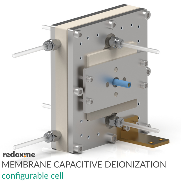
Membrane Capacitive Deionization configurable cell - MCDI configurable cell

Membrane Capacitive Deionization (MCDI) configurable cell has been designed to conduct research on removal of charged ionic species from aqueous or organic solutions (i.e., Desalination/Demineralization) via electrostatic (i.e., non-Faradaic) or electrochemical (redox) interactions. The MCDI cell contains two graphite current collectors that can serve as polarization electrodes. However, if the electrode material is the subject of research, it should be applied to an additional current collector, such as graphite paper or metal felt (not included in the product). Different electrode materials can be installed on both sides of the cell. If the thickness of these electrodes exceeds 250 micrometers, different gaskets are required. In such a case, please contact us for a solution.
The cell is designed in such a way that replacing the electrodes does not require removing the membranes or flow fields. It is enough to unscrew the plungers on both sides and replace the electrodes. In the standard configuration, the liquid in the main channel and side channels flows through the flow field cut from PEEK. However, these can be replaced with a porous material such as felt or a battery spacer, which will allow fluid flow. If work with materials of dimensions different from those listed in the specification is required, we can supply seals of different thicknesses or customize the cell. The cell allows for the installation of one or two ion-exchange membranes (not included in the setup). Their thickness is not critical, and it is not necessary to adjust the thickness of the membrane gaskets pressing them. The cell elements are constructed with inert materials to the sample (PEEK). It well fits aqueous (FKM gaskets and O-rings) and organic solvent (FFKM gaskets and O-rings) electrolyte requirements. The construction of the cell is gas-tight.
Application note
MCDI cell can be configured to allow the following cell architectures:
- Flow-by CDI consisting of: (i) two porous carbon or metal based current collectors coated with capacitive (e. non-Faradaic) material, and (ii) a main flow field enabling the feed water to be transported between electrodes. In this configuration, side flow fields and membranes are not installed.
- Membrane CDI consisting of: (i) two porous carbon or metal based current collectors coated with capacitive (e. non-Faradaic) material, (ii) two ion-exchange membranes (cation exchange membrane and anion exchange membrane) separating electrodes from the main flow field, and (iii) a main flow field enabling the feed water to be transported between electrodes. In this configuration, side flow fields are typically not installed. However, there are cases where installing both side flow fields is justified. All the graphics included in the product page refer to that configuration.
- Inverted CDI consisting of: (i) two porous carbon or metal based current collectors coated with capacitive (e. non-Faradaic) material where anode is treated for net negative surface charge and a cathode is treated for net positive surface charge, and (ii) a main flow field enabling the feed water to be transported between electrodes. In this configuration, side flow fields and membranes are not installed.
- Flow-electrode CDI consisting of: (i) two porous carbon or metal based current collectors with flowing electrodes made of capacitive (e. non-Faradaic) carbon suspension, (ii) two ion-exchange membranes (cation exchange membrane and anion exchange membrane) separating electrodes from the flow chamber, (iii) a main flow field enabling the feed water to be transported between electrodes, and (iv) two side flow fields for liquid electrodes. All the graphics included in the product page refer to that configuration.
- Hybrid CDI consisting of: (i) a Faradaic (e. battery) electrode for cation adsorption/desorption, (ii) a capacitive (i.e. non-Faradaic) electrode for anion adsorption/desorption, (iii) an anion exchange membrane placed adjacent to the capacitive electrode, and (iv) a main flow field enabling the feed water to be transported between electrodes. In this configuration, side flow fields and a cation-exchange membrane are not installed.
- Cation intercalation desalination consisting of: (i) two porous carbon or metal based current collectors coated with Faradaic cation intercalation materials, (ii) an anion exchange membrane separating electrodes, and (iii) a main flow field enabling the feed water to be transported between electrodes. In this configuration, one side flow field and cation-exchange membrane are not installed.
- Desalination battery consisting of: (i) two porous carbon or metal based current collectors coated with redox (e. Faradaic) material (one for cation adsorption/desorption and the other for anion adsorption/desorption), and (ii) a main flow field enabling the feed water to be transported between electrodes. In this configuration, side flow fields and membranes are not installed.
Specification
tubing size: 4 mm OD or 1/4 inch OD
fitting type: push-in, M5 male (4 mm OD) or Swagelok (1/4 inch OD)
electrode size: 60 mm x 60 mm (36 cm2)
recommended total electrode thickness: 200-250 µm
membrane size: 70 mm x 85 mm
maximum operating pressure: 20 bar
maximum operating temperature 150 ºC
Intrastat data
HS Code: 90278080
Country of Origin: Sweden
NET weight: 1300 g
Product includes
2 x stand, anodized aluminum
2 x plunger holder, SS 316L
2 x PEEK plunger
2 x tantalum current collector
2 x graphite current collector
1 x threaded end plate, SS 316L
1 x unthreaded end plate, SS 316L
1 x PEEK outer cell body
1 x PEEK inner cell body
1 x set of fittings
2 x female banana connectors, 4 mm dia.
1 x PEEK main flow field, 0.5 mm thick
2 x PEEK side flow field, 0.5 mm thick
1 x set of gaskets (FKM or FFKM) including:
1 x main flow gasket, 0.5 mm thick
2 x membrane gasket, 0.25 mm thick
2 x side flow gasket, 0.5 mm thick
2 x electrode gasket, 0.25 mm thick
Related products
ion-exchange membranes


