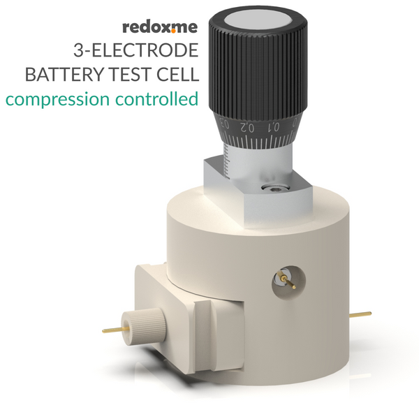
Dual Conductivity Test Cell - compression controled, T monitoring
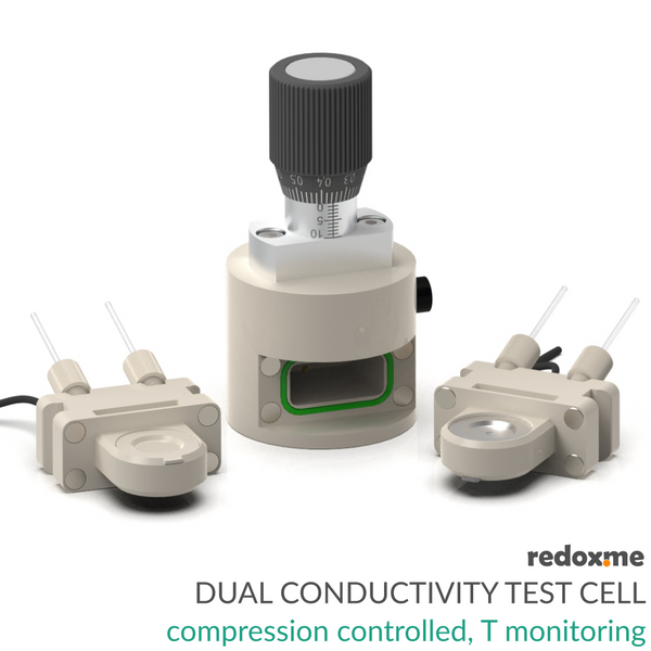


The Dual Conductivity Test Cell is a versatile, precision-engineered solution for comprehensive conductivity analysis in electrochemical materials. Building on the proven reliability of the standard redox.me Battery Test Cell, this system includes two interchangeable cartridges to provide dual measurement capabilities in a single platform:
a) in-plane conductivity cartridge designed for accurate measurement of lateral conductivity across your sample, ideal for characterizing thin films, membranes, and layered materials. Best for materials where lateral (surface) conduction dominates.
b) through-plane conductivity cartridge optimized for evaluating vertical conductivity, enabling insights into ion transport across the material thickness, which is critical in real device operation (like in batteries or fuel cells).
This modular design allows researchers to seamlessly switch between measurement modes without changing the base cell, ensuring consistent conditions and reproducible results.
The Dual Conductivity Test Cell can measure both electronic and ionic conductivity, but what it actually detects depends on how you set up the measurement and the material properties. In electronic conductive materials (e.g., graphite, graphene, conductive polymer, metal electrode), it measures the movement of electrons through the material. In ionically conductive materials (e.g., polymer electrolyte, ion-exchange membrane) in hydrated or in an ionically conductive environment, it measures the movement of ions (cations or anions) through the material. In that case, often, you need to condition the sample with a liquid electrolyte or humidify a membrane to allow ions to move. Note that the cell does not inherently distinguish between ionic and electronic conductivity and measures total conductivity. To separate ionic vs. electronic conductivity, you need additional techniques, like a) locking electrodes (e.g., non-reactive metal electrodes to block ion flow), or b) impedance spectroscopy with an appropriate equivalent circuit.
The cell elements are constructed with materials that are inert to the sample (Stainless steel and PEEK, FFKM O-rings). Gold-plated pins ensure good electrical contact. The construction is gas-tight and can be effortlessly assembled in the glove box, reducing possible human error to a minimum.
Application
The Dual Conductivity Test Cell is perfect for labs focused on battery materials, membranes, electrodes, and other electrochemical systems, offering both flexibility and high-precision performance. The measured material must be mechanically stable enough to fit into the cartridges and make good contact with the electrodes (liquids or very soft gels are generally not suitable unless confined in a solid matrix). With this setup, you can measure solid or semi-solid electrochemical materials where both in-plane and through-plane conductivity are relevant. Specifically:
a) membranes
- ion-exchange membranes (e.g., PEMs, AEMs),
- polymer electrolytes,
- separator films in batteries,
b) electrodes and films
- battery electrodes (cathode or anode composites),
- thin conductive coatings,
- graphene, carbon nanotube films, or conductive polymer layers,
c) layered or composite materials
- multilayered polymer/electrode assemblies
- laminated battery materials
- electrode-membrane interfaces
d) powder pellets or pressed materials
- compressed powders of ionic or electronic conductors
- ceramic or solid-state electrolyte pellets
The graph below shows the relation between the pressure applied to the sample and the distance travelled from the point of contact.

To calculate the point of contact, subtract the sample thickness from 4 mm. For example, for the 0.9 mm sample, the point of contact (i.e. reading on micrometer screw) will be 4 mm – 0.9 mm = 3.1 mm. Therefore, you should set the micrometer screw to 3.1 mm and measure the distance/pressure relation from this point.
The procedure for conducting the measurements with a similar setup and the method for calculating in-plane conductivity are included in this measurement protocol.
Specification
maximum sample thickness: 2.5 mm
spring rate: 10.86 N/mm
maximum spring load: 90 N
operating temperature: -40°C – 80°C (default)
in-plane conductivity cartridge
maximum sample diameter: 22 mm
recommended sample diameter: 20 mm
minimum sample diamater: 15 mm
electrode assembly: 4 x wire
electrode spacing: 2.5 mm
electrode length: 10 mm each
electrode wire diameter: 0.6
electrode material: platinum
through-plane conductivity cartridge
maximum sample diameter: 22 mm
recommended sample diameter: 20 mm
minimum sample diameter: 18 mm
electrode assembly: 2 x round plate
electrode material: platinum
electrode size: 18 mm dia.
electrode thickness: 0.5 mm
Intrastat data
HS Code: 90309000
Country of Origin: Sweden
NET weight: 400g
Product includes (depending on the selected option)
1 x battery test cell base from that product (no cartridge included)
1 x set of cable adapters 1mm to 4mm banana plug
in-plane conductivity cartridge
1 x cartridge body with 4 platinum wire electrodes installed
1 x PEEK plunger
1 x Pt100 resistance temperature detector (reader not included)
through-plane conductivity cartridge
1 x cartridge body
1 x upper electrode plunger, Stainless Steel 316L
1 x lower electrode plunger, Stainless Steel 316L
2 x platinum electrodes, 18 mm dia., 0.5 mm thick
1 x sample lock ring, PEEK
1 x Pt100 resistance temperature detector (reader not included)
1 x electrode plunger removal tool
Related products
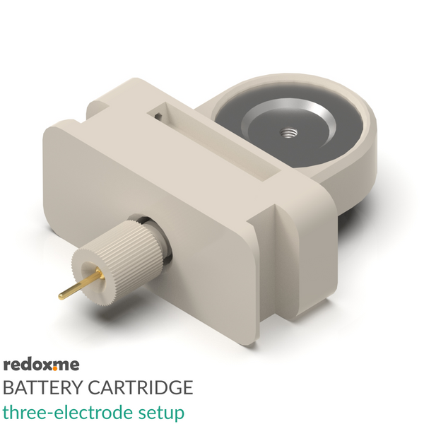
Battery Cartridge – three-electrode setup
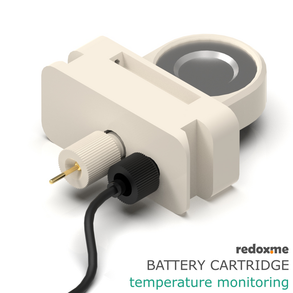
Battery Cartridge – temperature monitoring
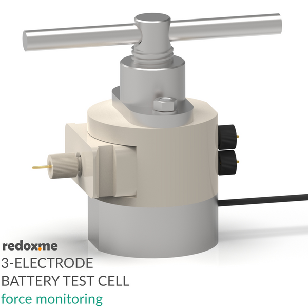
Three Electrode Battery Test Cell – force monitoring